Reality Capture Needs a Control Plan Before It Can Prove Progress
A practical evidence plan for Iranian projects that makes repeat scans, photographs, and point clouds comparable, reviewable, and fit for progress and quality decisions.
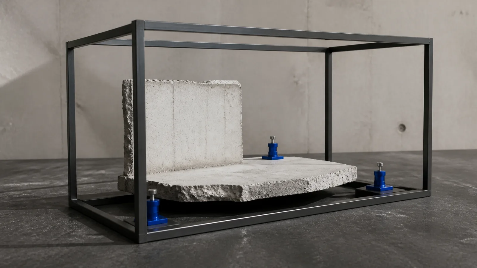
A dense capture is not automatically reliable evidence
ISO 17123-9 defines field procedures for evaluating the repeatability of terrestrial laser scanners and their ancillary equipment for building, civil-engineering, and surveying work; it also says those checks are only a first step in evaluating measurement uncertainty. ASTM E3125-17(2025) addresses point-to-point distance performance for a defined class of medium-range 3D imaging systems. Both sources make the same management point: the instrument and task must be tested together; a dense point cloud does not certify itself. [1][2]
Reality capture can make site state visible, but visibility is not proof of quantity, quality, completion, or payment entitlement. A scan cannot see reinforcement after concrete, verify a certificate, decide whether an incomplete assembly meets the contract, or explain why a surface moved between two dates. OlbrichCo’s operating view is to commission a measurement chain: decision, tolerance, reference frame, capture, validation, interpretation, approval, and retained evidence. The camera, scanner, phone, or drone belongs in the middle of that chain.
Start with the decision and its tolerance
USIBD’s Level of Accuracy Specification Version 3.1 places renewed emphasis on selecting the required accuracy from the project tolerance and on communicating tolerance through standard deviation. The 2024 ASPRS positional-accuracy framework is sensor-agnostic and supplements its core requirements with guidance for field surveying, photogrammetry, lidar, uncrewed aircraft systems, and oblique imagery. The useful lesson is to specify the decision and required performance before selecting the capture method. [6][7]
Write a capture requirement for each use case. Façade plumbness, earthwork volume, installed-services clearance, concealed-work records, and visual weekly progress do not need the same accuracy, coverage, timing, or reviewer. A photo that is adequate for a narrative report may be unsuitable for quantity calculation; a geometrically accurate surface may still be unable to prove the product, inspection status, or contractual completion of the work it represents.
- Decision: define the design, release, quality, progress, payment, safety, or operating action that will use the capture.
- Measurand: name the point, edge, surface, volume, clearance, count, condition, or installed location actually being evaluated.
- Performance: state units, tolerance, uncertainty or accuracy expression, coverage, exclusions, and independent validation method.
- Authority: identify who captures, processes, checks, interprets, accepts, and may reopen the decision.
Fix one reference frame before the first progress capture
The USGS Lidar Base Specification 2025 Revision A separates datum, coordinate reference system, units, point-source identity, absolute accuracy, internal precision, checkpoints, and metadata rather than treating ‘georeferenced’ as a single property. IFC 4.3.2 likewise provides project global positioning through a recognised coordinate reference system, eastings, northings, elevation, datums, orientation, and a defined mapping from the project engineering coordinate system. [4][5]
For a building site, issue a short survey-control record before recurring capture begins. It should define the project grid, horizontal and vertical datum, origin, north rotation, units, transformation parameters, permanent and temporary control points, responsible surveyor, protection and reinstatement rules, and the coordinates used by design models and setting-out teams. Keep local working coordinates where they make engineering software stable, but preserve an approved, testable transformation to the project reference system.
Do not use the same points both to fit a capture and to declare it accurate. Reserve independent check points outside the registration solution and distribute them across the area and elevation range that matter to the decision. If control is damaged, shifted, hidden, or replaced, stop comparison, re-establish it through the responsible survey process, and record the change. A clean visual overlay on a wrong reference frame is a precise-looking error.
Commission the method under actual site conditions
ISO 17123-9 treats field verification as a check that a terrestrial scanner is suitable for the immediate task. ASTM E3125 evaluates combined angular and range behaviour through point-to-point tests and recognises that performance can be assessed under different surface and environmental conditions. USGS guidance for uncrewed-aircraft imagery explains that ground-control accuracy and tie-point quality directly affect geometric accuracy, irrespective of image ground-sample distance. [1][2][3]
Run a witnessed trial on representative geometry before production. Include dark, reflective, repetitive, narrow, high, dusty, moving, and partly occluded conditions where they occur. Compare derived dimensions or surfaces with traceable independent measurements; record instrument identity, firmware or app version, settings, environmental conditions, control used, processing version, operator, and residuals. Recheck after repair, impact, software change, long transport, or a material change in the task.
Choose the least complex method that closes the decision. Fixed photographs may be enough for visual sequence; calibrated photogrammetry can serve appropriate dimensional tasks; terrestrial or mobile scanning may suit dense geometry. Airborne capture introduces separate questions of flight permission, access, privacy, safety, weather, and competent operation. Verify current Iranian requirements and site authorisations before any flight; where safe or lawful access is uncertain, design a terrestrial route instead of making a drone essential to the control plan.
Repeat the coverage, not only the date
USGS calibration guidance calls for documented acquisition and quality control because weakly controlled imagery can be difficult to combine with other geospatial data. The 2025 Lidar Base Specification treats collection conditions, overlap, data voids, source identification, survey points, validation, and metadata as explicit parts of the deliverable. Repeatability therefore depends on both geometry and records, not on saving another large file. [3][4]
Create a capture route and scene-readiness checklist. Define stations or paths, view direction, overlap, height bands, lighting window where relevant, required clear zones, temporary-work status, moving-plant controls, and surfaces that must not be obstructed. Mark every void and exclusion rather than filling it by assumption. When weak connectivity is expected, capture and validate locally, retain immutable originals, and synchronise controlled derivatives later without losing timestamps, identities, or processing history.
- Before capture: verify control, access, safe separation, scene readiness, device time, storage, battery, and required permissions.
- During capture: record stations or paths, control observations, gaps, moving objects, weather or lighting changes, and exceptions.
- After processing: report registration residuals and independent check errors, inspect critical interfaces, and quarantine failed areas.
- At issue: retain originals, approved derivative, coordinate and unit declaration, software version, operator, checker, date, and limitations together.
Separate observed change from contractual progress
A comparison engine may detect a new surface, missing volume, or movement beyond a chosen threshold. That result is an observation, not yet a commercial or technical decision. Temporary works may appear as progress; delivered but uninstalled material may be absent; completed services may be concealed; demolition may reduce volume while advancing the programme; and accepted work may still depend on tests, documents, or approvals that geometry cannot see.
Use a three-state workflow: machine-observed change, professionally interpreted work state, and contract-authorised status. Link each accepted quantity or quality decision to the capture area, calculation method, exclusions, applicable drawing or work-breakdown item, inspection evidence, reviewer, and signed record. Define how rework, occlusion, temporary items, out-of-sequence work, and later corrections are handled. The signed contract and governing measurement rules control payment; the capture is evidence within that process, not a replacement for it.
Pilot one repeatable zone and measure evidence quality
Choose one consequential, measurable zone: a façade bay, structural floor, plantroom, earthwork cell, or repeated apartment type. Capture a baseline and two real updates using the approved control, reserve independent checkpoints, process with versioned settings, review one apparent change and one known exception, export an open derivative, and ask a second competent person to reproduce the decision from the retained record.
Keep the scorecard small: control points verified before capture; planned area with usable coverage; independent checks within the stated limit; critical surfaces classified as observed, occluded, or not applicable; processing turnaround; suspected changes confirmed or rejected by review; decisions with complete evidence links; and time for another reviewer to retrieve and reproduce a result. Show denominators and error distributions, not only average residuals.
The point of view is firm: reality capture becomes valuable when it reduces uncertainty in a named decision, not when it maximises pixels or points. It does not replace setting-out surveys, statutory inspections, material tests, concealed-work hold points, design responsibility, or contract administration. Final methods, tolerances, sampling, permissions, safety controls, measurement rules, acceptance, and retention must follow applicable Iranian requirements, the signed contract, actual site conditions, and review by the responsible survey, design, construction, quality, and commercial professionals.
Sources & further reading
These primary sources support the claims and implementation frameworks used in this field note.
- 1. ISO 17123-9:2018 — Field procedures for testing terrestrial laser scanners
International Organization for Standardization
- 2. ASTM E3125-17(2025) — Point-to-point distance performance of spherical-coordinate 3D imaging systems
ASTM International
- 3. Guidelines for calibration of uncrewed aircraft systems imagery — USGS OFR 2023-1033
U.S. Geological Survey
- 4. Lidar Base Specification 2025 Revision A
U.S. Geological Survey
- 5. IFC 4.3.2.0 documentation — Project Global Positioning
buildingSMART International
- 6. Level of Accuracy Specification Version 3.1
U.S. Institute of Building Documentation
- 7. Positional Accuracy Standards for Digital Geospatial Data — Edition 2, Version 2 (2024)
American Society for Photogrammetry and Remote Sensing
Sources were checked on 24 August 2026. They describe international measurement and documentation practice; they do not create legal requirements for an Iranian project. Capture methods, error limits, flight or access permissions, payment basis, and final acceptance must follow applicable Iranian requirements, the signed contract, the safety plan, actual site conditions, and responsible professional review.